• A few people have been scammed on the site, Only use paypal to pay for items for sale by other members. If they will not use paypal, its likely a scam NEVER SEND E-TRANSFERS OF ANY KIND.

Horn upgrade

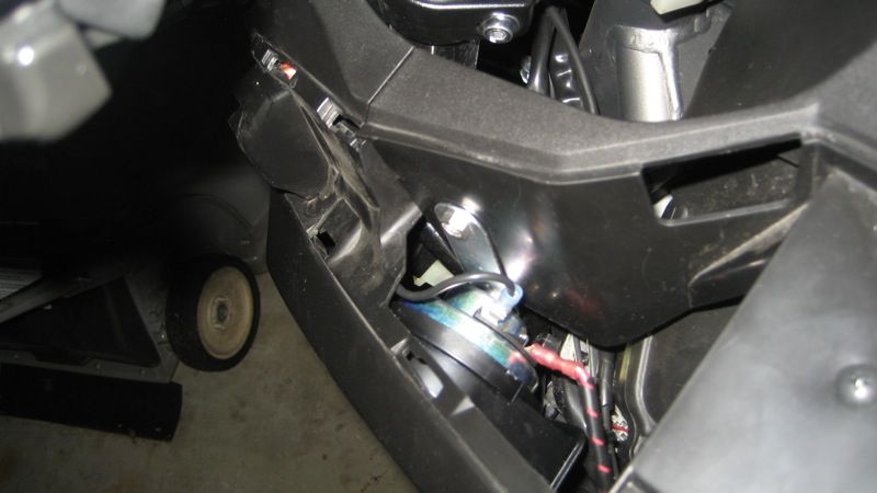
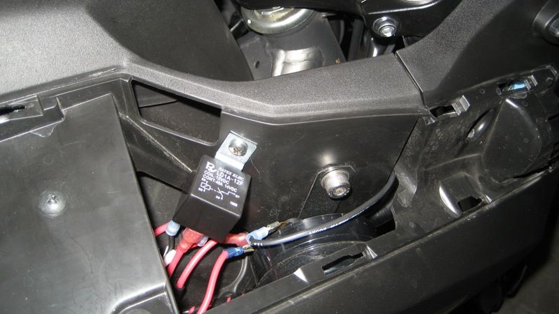
Placing the relay is easy, since it's so small. The horn is the challenge. The obvious place is under the air intake cover, but I haven't been able to figure out how to remove the cover. Any help from you guys would be appreciated.

The other bit of information is the source of the relays, inline fuse holder, etc. I went to Amazon under the automotive category and searched for the NC-700 and also for motorcycle horns. One of those two should find the goods for you. These items were just a few dollars, so it's a very quick and easy place to order from.

Amazon is a good search location, because you may find other bike related stuff while you're looking. I've learned to look there first for almost everything and usually end up successful. And their return policy is second to none in my opinion, especially on more expensive items.

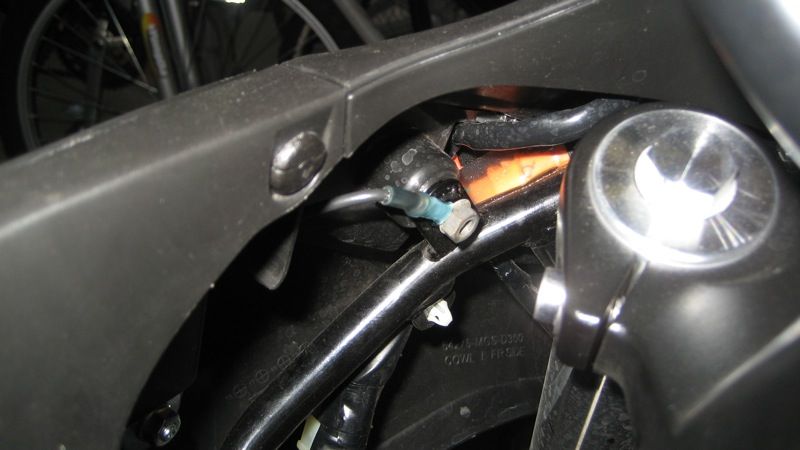
I think there is enough space under the right fake air duct. If you want to mount two of them, the left side is empty too. There is a push type trim clip on the inside of the triple clamp opening and there is one screw accessible under the luggage compartment lid. After these two are removed, slide the air duct rearward to clear the tabs. None of this stuff is NC-700 specific. They are common automotive parts. Another place where a single horn can be mounted is the stock horn location. I mounted one of my two Fiamms there (the high one). To tuck it in higher, I located the metal mounting strip behind the bolt that the original horn mounting strip was attached to by running a bolt through the front and putting a nut on the backside. It places it about 3/4" back and looks a bit neater. I pointed the bell downward.
 
Another place where a single horn can be mounted is the stock horn location. I mounted one of my two Fiamms there (the high one). To tuck it in higher, I located the metal mounting strip behind the bolt that the original horn mounting strip was attached to by running a bolt through the front and putting a nut on the backside. It places it about 3/4" back and looks a bit neater

A close picture of this would be appreciated, Beemer, I have still to decide where I will place the horns.
 
A close picture of this would be appreciated, Beemer, I have still to decide where I will place the horns.

Here is the high pitch horn mounted to the back side of the original mounting nut...

DSC00771.jpg

Here is the open area under the right side fake air duct (yours will not be full of relays)...

DSC00772.jpg
 
Beemer, I see in the picture you pointed the bell downward, and I see as well that the horn terminals are pointed down too... My horns have the terminals in the opposite side of the bell, not like yours, so I'm concerned with the terminals being too exposed. Did you turn the bell plastic, or you got it that way from the manufacturer? If you turned it, I'm interested in the method you used; mines seems to be glued and I'm out of ideas on how to turn them

BTW: thanks for the pictures, now I see what you did with the mounting
 
Beemer, I see in the picture you pointed the bell downward, and I see as well that the horn terminals are pointed down too... My horns have the terminals in the opposite side of the bell, not like yours, so I'm concerned with the terminals being too exposed.

I would not worry about the terminals. They will get a pretty good bath in either mounting orientation. You can help the water-proofness of them by coating them with dielectric connector grease. I think pointing the bell down is more important to prevent them from filling with water. The horns are designed for an under-hood mounting where water spray is expected.


Did you turn the bell plastic, or you got it that way from the manufacturer? If you turned it, I'm interested in the method you used; mines seems to be glued and I'm out of ideas on how to turn them

No, I do not think that they can be rotated. It may be random location from the factory, but I believe it is set at manufacture. My high pitch horn is about 35 degrees from the bottom and my low pitch horn is about 90 degrees from the bottom.
 
Last edited:
I could not leave one horn without a mate and installed a Fiamm Low Tone Highway Blaster in the corresponding left side open space under the air duct.

IMG_8922.jpg


Two horns require a relay which gets the most sound out of the horns and also to protect the contacts in the horn switch. I mounted a four pin relay in the right space near the horn.

IMG_8924.jpg


The wiring connections were previously described by Lee but to repeat .... the original wires to the little Honda horn I earlier extended up into this space and connected to the first Fiamm. I took those two wires off that horn and connected to terminals 85 and 86 of the relay. Pressing the horn button now closes the contacts in the relay ...... and allows a clean supply of switched 12v power to flow from the battery to the accessory fuse block then to terminal 87 on the relay ...... across the relay and out terminal 30 to the right horn. I slipped a piggyback male terminal fitting on the right horn positive terminal so 12v also flows to the left horn from the right one. Using a four pin relay meant connecting the two positive terminals on the horns together. Use of a five pin terminal would give two separate output terminals - one for each horn and the two horns would not have to be interconnected like I did. Either way is OK. The last connection is grounding the horns so the circuit is complete and sound is created.

The collared bolt that fixes the side panels with the Honda wing on them threads into a nut welded to the fairing stay. A portion of this 8 mm bolt protrudes out the inner side of this nut. I made two ground conducters with a ring terminal on one end and a female spade terminal on the other. The horn end is connected to the male spade terminal on the horn and the ring terminal goes under an 8 mm x 1.00 nut threaded onto that bolt. Be careful tightening this nut as it only threads about halfway onto end of the bolt and would be easy to strip.

IMG_8925.jpg
 
Beemer and dduelin,

With that location plenty of toys, is it not very difficult to get to the two clips that hold in place the side body pannel? I see Beemer has velcro there, so in his case hi could retire the relays to gain access to the clips, but what about you dduelin?
 
The relay and the horns will come out or off with one fastener each, a screw for the relay and a bolt for the horn.
 
Beemer and dduelin,

With that location plenty of toys, is it not very difficult to get to the two clips that hold in place the side body pannel? I see Beemer has velcro there, so in his case hi could retire the relays to gain access to the clips, but what about you dduelin?

Yes, that is the reason for the velcro. Not only is the access helpful for clip removal on the side covers, but the item you are bolting to is the outside wall of the center cover which must be removed for maintenance of the air filter.
 
Probably you have your own method to deal with the clips hidden in that area but, just in case this helps somebody, this is the trick I use to reinstall them:

IMAG0180.jpg


Of course, with the pliers configured for just a little bit pressure.

Try it, you wont be dissapointed

HTH
 
Maybe you also want to have a look at this (I didn't order it, but I was thinking about it for a while):

REMINDER FOR INDICATOR - Louis - Motorcycle & Leisure

HTH

I think in many ways the Audicator is a better product. The beep can be programmed to stay off for a set amount of time after the signal is turned on. As long as the brakes are applied it won't beep. If your turn is interrupted a touch of the brake lever resets the timer. Lastly the beep gradually increases in volume rather than just starting to scream at you.
 
Here's my version of the horn upgrade. It follows from what others have done, with a little twist in the mounting method.

I found there were two brackets that held nothing but loose electrical cable guides near the steering head. Wire ties substituted nicely for holding the cables, and left the brackets free for horn mounting. Now the Fiamm High and Low Tone Freeway Blaster instructions said "do not bend or shorten the bracket", I bent them AND shortened them. So, logically speaking, I didn't violate the rules. My modified horn brackets attach with one metric screw and self locking nut each, but a bent tab on the end of the brackets keys the bracket position. I later painted the horn brackets flat black.

Mounting the horns to the frame frees up the center cover for easy removal. In Honda bodywork style, I mounted the horn relay with a Honda body clip. Remove the one clip to free the relay, and the center cover then removes as it normally would. No need to touch the Fiamm horns. Also, the clips for the side panel removal are not blocked by the horns, but you might need some small hands to reach in there.

I left the stock horn live as well. So now there's a low tone, high tone, and as Beemerphile put it, a clothes dryer buzzer, all sounding at once. The Fiamm horns run off the same added circuit as my frunk 12 volt outlet, wired straight to the battery with an in-line fuse. I read 12 amps on the Fiamm circuit with the horns blowing, so I fused it at 15 amps. The wire size I used is probably overkill, but everything was stuff found around the house.

Man, there sure is a lot of wasted space inside these body panels; there's plenty of room for accessories. In fact, on non-ABS models there's a big empty hole above the transmission, too.

See the pics!

Greg

100_4889s.jpg100_4896s.jpg100_4924s.jpg100_4925s.jpg100_4929s.jpg
 
Last edited:
Installed the WALO dual tone air horn ( it is too big for the frunk side area). Found the area under the frunk where the ABS unit would be on the DCT (US model). This area is near the speed sensor and the area is quite large. Separate power feed (20 amp) and relay were used.

IMG_2110.JPG


If your having an orientation problem, go to the counter shaft cover look up and in from there. This open area is directly above the transmission.
 
Last edited:
I went a slightly different route. I used a water resistant mostly sealed boat horn and relayed it off the OEM horn as well as ran it through a fuse box (which was relayed to work off of ignition). The beauty of mine is that it's out in the open so that it looses no volume to muffling and it's extremely water resistant. It's not as loud as the Stebel Nautilus that I have historically installed in all my bikes, but I'm guessing that it has a much lower chance of failure since it's water resistant and not compressor driven.

This particular mounting only works with the Givi crash bars (at least as I have it shown) but it makes it a stupid easy install (minus the relay configuration and wiring). When I hit the horn button, I have 3 horns blow and it's still louder than a car horn. I'm quite happy with it. I'll probably remove the brand stickers and just leave the stainless steel housings. IMAG0032.jpg
 
I am tempted to install a louder pair of horns (snail horns), but then over here in Switzerland, we seldom use the horn at all (unlike Italy or Spain). :p
To be honest, I have had the bike since April 2012 and with 5000+km, and I have NEVER used the horn even once.
:p
 
I am glad I saw this thread. I am considering this for the Nic and my Virago.

What do you think I should look for in terms of the electrics for this?
Screaming Banshee - Loud Motorcycle Horns and Safety Systems

The horn part of the Banshee looks a lot like the WALO air horn and several others that are renamed or repackaged.
The flashing light function ties into, the light circuit with their control box.

Most need a relay and 15 or 20 amp circuit. The stock button or stock fuse not likely to able to carry the extra current.
 
Back
Top