• A few people have been scammed on the site, Only use paypal to pay for items for sale by other members. If they will not use paypal, its likely a scam NEVER SEND E-TRANSFERS OF ANY KIND.

Skene IQ 275A controller help.... Please.

76Hawke

Site Supporter
Joined
Apr 14, 2019
Messages
152
Reaction score
107
Points
43
Location
Cleveland
Visit site
So I picked up a pair of Cyclops Pegasus auxiliary lights, and the skene IQ 275-A controller. I don't have the Honda accessory sub harness, but I'm thinking about adding it if I don't use a different fuse block or an m-unit . I was hoping to do the fuse block or sub harness as a winter project, and for the time being I was hoping to just add the auxiliary lights hooked up to the IQ 275a straight to the battery for fall driving.
Does anybody have experience with this that they'd be willing to share?
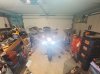
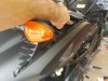
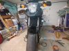
I mounted both of the lights, and wired them to the controller. I took both of the lights and grounded them to the frame, as well as the black lead from the controller.
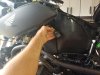
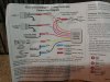
I now have a white wire that I am supposed to tap into my high beam. I also have a red wire that calls for me to tap into a switched power source.
Can anyone break down for me what that switched power source would be, and where I would best tap into both the switched power source, and the high beam? Thanks again for any help, and I'd be grateful to answer any questions that might help with the process.
Also, is it silly that I'm hesitant to use positaps?
Thanks in advance
 

Attachments

  • 15672262861563993052869927750471.jpg
    15672262861563993052869927750471.jpg
    94 KB · Views: 60
  • 15672263622574218194433504294120.jpg
    15672263622574218194433504294120.jpg
    94.6 KB · Views: 61
Last edited:
Loving the result when I cheat and touch the red wire right to the battery, but I'm hoping to get some hours riding this weekend, and the loose wires won't do.
Thanks again
 

Attachments

  • 15672272153943969910700239197961.jpg
    15672272153943969910700239197961.jpg
    90.8 KB · Views: 57
I started getting the posi-tap connectors in kits a few years ago. So far no problems with them. Before I used the blue quick splice but always put a dab of dielectric grease in it to help lessen problems down the road. I have the Denali lights that look like yours without the skene controller.

Sent from my SM-N960U using Tapatalk
 
I use the Skene along with the Innov PowerHub (which is the fuseblock for my purposes). For the switched power source I tapped the pink and blue wire coming out of the turn signal relay is conveniently located on the rear wall of the left fake vent.
 
For the switched power source I tapped the pink and blue wire coming out of the turn signal relay is conveniently located on the rear wall of the left fake vent.
Thanks so much for taking the time to reply.

Adding pictures of exactly what you're talkin about, so that some other helpless soul might also gain from your shared knowledge.

Do you happen to know which wire I should tap into for my brights? I'm definitely learning here, and I tried referencing a wiring schematic I found,but the schematic simply shows two blue wires going into my headlight assembly. when I look at the back of my headlight however, I see a blue wire and a blue with silver markings. The Skene directions say to tap into the bright light with my white wire, but again I'm not sure which one is the bright.
Last question... I hope and think. Would tapping into the wires right behind the bulb assembly be a good place, or do you have a better suggestion? Really appreciate your time,
Matt
 

Attachments

  • 15672846688141932926226327807876.jpg
    15672846688141932926226327807876.jpg
    91.7 KB · Views: 43
  • 15672847808712851742986008923521.jpg
    15672847808712851742986008923521.jpg
    91.2 KB · Views: 44
I’d have to look, but I’m pretty sure I tapped the hi beam wire near the bulb.


Sent from my iPhone using Tapatalk
 
Give yourself room to be able to change out the bulb. I tapped back as far as I could. I will pull out the electrical drawings.

Sent from my SM-N960U using Tapatalk
 
Looking at the drawing the solid blue is Hi beam. The blue/white light is power to the headlight going through the dimmer switch. The white wire is low beam.
ad62b5359276b3b9a7c2f969bb1b0024.jpg
501789e77819a376e9a5dd718d07f6bb.jpg
50e137d5b1a8deff14a37fc8b42f28fc.jpg


Sent from my SM-N960U using Tapatalk

So I will splice into the solid blue then. Your short explanation was enough to help me understand that schematic tons better.
Really grateful for the help, hacking at my baby blind is not something I wanted to do.
Reading these forums for HOURS has taught me tons, but taking the time to answer my specifics is super helpful!
 
Back
Top