JoeZ
Site Supporter
link for that? I think I'd like to try the SAE (battery tender) connection method. Would not be hard to wire in a simple ON/OF switch and make it manual.
Maybe we could put together a list of things required to accomplish it?
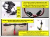
To install "Fog Lights" using "Battery Tender Wiring" (experimental stage
")
2 Fog Lights (with Red and Black Wires).
1 (preferable 10 Gauge) 2 Pin Quick Disconnect Wire Harness - SAE Connector (to cut in half and connect each end of the Tender wires to the two separate Fog Light Wires).... Red to Red and Black to Black).
2 Pin SAE to SAE Splitter Cable-for Battery Tender Harness Charge 2 items
(To Connect Both Lights into One tender cable).
Motobatt Battery Tender SAE connector 1 into 2 "Fused" Splitter Cable (1 wire is 7.5amp and the other is a 15amp wire).
(Fog Lights Wires will use this to Connect into the 15amp wire which gets connected to the Bike's Battery via the Tender wire).
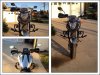
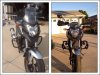
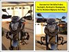
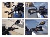
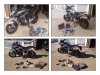
Look at the attached picture to see how simple it should be. I ordered everything and will report how it goes.
Not sure how to add a "On/Off" switch? But worse comes to worse, I can just disconnect the Tender connections when I want to turn the Fog Lights off and re-connect when I want the lights on). Should work (I think).
Gotta read up on how to fuse two separate wires together
but best part is I don't have to take apart my NC 700 to wire it up or pay a tech $80 an hour. And no, my NC didn't come with an attached tender wire.Sent from my iPhone