• A few people have been scammed on the site, Only use paypal to pay for items for sale by other members. If they will not use paypal, its likely a scam NEVER SEND E-TRANSFERS OF ANY KIND.

How I installed: lights, horns, powerlet, jumper cable quick connect

JoeTx

Site Supporter
Joined
Oct 21, 2013
Messages
240
Reaction score
0
Points
0
Location
League City Texas
Visit site
First, many many thanks to those who posted before me: Brillot2000, ddulin, Bamamate, Beemerphile without their help this install would have not gone as smooth as it did.

First soldering, I used no crimped fittings for this install, everything was soldered and here is how I solder:

063.jpg
Fray the ends and twist a strand of wire around to hold it together tight
2014_05_03_12_42_07_ProShot.jpg
065.jpg
Solder
056.jpg
Dab of hot glue
2014_05_03_14_58_56_ProShot.jpg
Slide heat shrink over while glue is soft and heat
2014_05_02_15_07_00_ProShot.jpg
Lug that I made
020.jpg
Jumper for horn install
022.jpg
044.jpg
Necessary tools: work holder and loupes

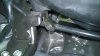
Horn Install: I found the horn install the most challenging, finding a mounting solution was most troublesome when out of no where I noticed a welded nut on the frame that had nothing connected to it, don't know what's it for, don't care. And to my amazement there was on on the other side!
wiringdiagram.jpg
WP_20140502_09_13_35_Pro.jpg
006 copy.jpg
007 copy.jpg
I had to slide the horns in from the left hand side because of their size
029.jpg
Right side
WP_20140503_10_52_47_Pro.jpg
Left side
I attached them with some bolts I bought at the auto parts store: Dorman 980-216
080 (2).jpg
087.jpg
From previous posts I knew already that I would have to use the connections at the old horn, I ran 2 wires along side the O2 sensor cable over in front of the battery to the left of the bike, all relays were to be there, I put the wires in a housing I bought at Fry's.
072-1.jpg
I attached a fused (7.5amp) power supply to the positive battery terminal for the horn and lights, used a separate one for the powerlet.
071.jpg
All my relays were going to be placed near the accessory outlet in the frunk, now for the connection:
032.jpg
034.jpg
Left it loose to test my connections and when satisfied soldered it all together.
069.jpg
Powerlet: I wanted a separate high amp accessory outlet for air compressor and such and wanted keyed with a relay so I could not accidentally leave something plugged in and drain the battery.
011.jpg
072 copy.jpg
083 (2).jpg
Right under the Honda accessory is the main ground for the bike I used it for all the grounds. (negatives-)
084 (2).jpg
Lights: I basically copied Brillot2000 light install, 2 10w LED's, bar mounts (ADVmonster), Senke Design Intelligent Lighting Controllers they were powered from the same source as the horns
simple, simple install, the Honda accessory kit included both a keyed source for power and an extra high beam connection, the honda shop manual has a fantastic schematic

WP_20140502_09_14_43_Pro.jpg
WP_20140502_09_14_50_Pro.jpg
083.jpg
086.jpg
039 copy.jpg
040 copy.jpg
069 copy.jpg
074.jpg
075.jpg
Low Beams High Beams

Jumper cable connector: Ordered my jumper cables from CV Supply on ebay bolted right up to battery and my favorite negative connection super easy and never have to worry about a jump, alas no soldering :(

072 copy.jpg
084 (2) copy.jpg
085 (2).jpg

015.jpg 080.jpg
Before After
 

Attachments

  • 006.jpg
    006.jpg
    62.4 KB · Views: 1,986
Last edited:
nc1.jpgnice! but lot of work. i wouldn't do it. too lazy . those horns look pretty small. will they fit inside side cowls? one probably can mount them on that black metal frame?
 
View attachment 17352nice! but lot of work. i wouldn't do it. too lazy . those horns look pretty small. will they fit inside side cowls? one probably can mount them on that black metal frame?

That was my first choice, out front somewhere, but they're huge. Was just going to bolt them to the cross bar of my SW motech engine guard till I found those fittings. That front cowl looks promising but once again those rascals are big!
 
Wow! Fantastic work! :cool: :D

Thanks so much for taking the time and effort to post up all the great pictures and step by step, Joe. I know how that can be very tedious, when all you want to do is finish the darned thing ;)
 
we have 2005 Mercedes e320 and looks like there is a 420 hz single horn. sounds really nice(at least to me) and loud. most likely will fit NC's OEM place and probably no relay required

2000-2006 Mercedes S500 Horn - Body Electrical - Vemo 00-06 S500 Horn - 6452-01160846 - PartsGeek

bosch is a bit more expensive,but same hz

05 2005 Mercedes E320 Horn - Body Electrical - Bosch - PartsGeek

probably can be found on junk yard,but they won't give it to you for free anyway.

i was thinking about installing one instead of OEM. kind of lazy way around weak oem horn ;)
just a thought.
yours would look awesome under the hood of any car. thru the grill.
 
Nicely done!

What is the power consumption of the horns? I just replaced mine with a single alarm siren, uses about 10W.
 
we have 2005 Mercedes e320 and looks like there is a 420 hz single horn. sounds really nice(at least to me) and loud. most likely will fit NC's OEM place and probably no relay required

2000-2006 Mercedes S500 Horn - Body Electrical - Vemo 00-06 S500 Horn - 6452-01160846 - PartsGeek

bosch is a bit more expensive,but same hz

05 2005 Mercedes E320 Horn - Body Electrical - Bosch - PartsGeek

probably can be found on junk yard,but they won't give it to you for free anyway.

i was thinking about installing one instead of OEM. kind of lazy way around weak oem horn ;)
just a thought.
yours would look awesome under the hood of any car. thru the grill.

Thanks, yeah this install was a lot of work, crimp connections would have been a tad quicker that's why I saved up and did all my electrical at one time.
 
First, many many thanks to those who posted before me: Brillot2000, ddulin, Bamamate, Beemerphile without their help this install would have not gone as smooth as it did.

First soldering, I used no crimped fittings for this install, everything was soldered and here is how I solder:

View attachment 17324

Fray the ends and twist a strand of wire around to hold it together tight

View attachment 17327
Solder

Looks Good!!! I personally prefer using crimp contacts for all my electrical contacts.
 
Hey JoeTx
Great pictorial. Thanks!! I will be using this posting for some of the things I want to do to my bike in the near future.
Just ONE little tiny recommendation to avoid some really upsetting and embarrassing moments when using your great soldering technique.
Unless you really, really like doing things twice.....ALWAYS remember to slide your heat shrink sleeve over one of the wires BEFORE soldering everything up. It continues to surprise me how this is such an easy step to overlook!
It is a major PITA to have to cut or unsolder the nice connection you just made to install the heat shrink. :mad:
DAMHIK :rolleyes:
Thanks again!!!

Your welcome, Yeah in some of the photos there was no heat shrink I think I was trying to show the technique. BUT always always have the heat shrink on before you solder and up out of the way, those wires become hot too.
 
Looks Good!!! I personally prefer using crimp contacts for all my electrical contacts.

I too prefer crimping, keeps the wire flexible and less prone to breaking during vibration, not to mention faster and easier (With the right tools... a hammer is not the right tool, nor is a pliers or channel lock.)

But to each their own, a quick Google suggest that crimp vs. solder can be a just as heated of a debate as any oil thread... Also that NASA has a standard for
"CRIMPING, INTERCONNECTING CABLES,
HARNESSES, AND WIRING
"


Either way the install looks very nice. Quality craftsmanship is always appreciated, even if it isn't the way I'd do it. (though that should have been implied with the word "quality" ;) )
 
"Also that NASA has a standard"

Thought this a little weird, Joe Tx lives just out side of NASA gates, and works in Clear Lake where NASA takes its real human mistakes.

I ride some in the dirt, and have now re-done the wiring on my Givi running lights four times. Like anglachel, I like the crimps, but for the dirt next time I solder.

Also, see Joe Tx has put on some dirt riding foot pegs.
 
Last edited:
"Also that NASA has a standard"

Thought this a little weird, Joe Tx lives just out side of NASA gates, and works in Clear Lake where NASA takes its real human mistakes.

I ride some in the dirt, and have now re-done the wiring on my Givi running lights four times. Like anglachel, I like the crimps, but for the dirt next time I solder.

Also, see Joe Tx has put on some dirt riding foot pegs.

Funny you should mention this, I got this technique from a NASA site, this is the only approved method for soldering NASA allows. Just getting ready for WABDR with those pegs, been practicing those videos you posted.
 
Way off topic.

Thanks a million! I didn't even make it past the part about using hot glue at the beginning. I've been trying, not too hard, to think of a way to make the frame of my clics glasses (ClicMagneticGlasses.com FREE Shipping on Clic Readers & Sunglasses) stickier so that the shrink tubing I've been using to hold them together after they break won't slide off. I'm trying this after I get home from work. Now to go back and read the rest of your post.
 
Back
Top